05-09-2011, 07:55 PM
I received a trial issue of of Model Railroader today (June 2011). In it I found an article By Tony koester called Trains of Thought. In it he writes about using A micro switch to set the polarity and hold the point rails in place. I was doing something very similar in a section of my layout where access to the underside of the layout restricts the use of the homemade switch machines that I was using. In other places on the pike I have used a switch machine inspired by Gary S. His idea uses a 3 way switch mounted on an aluminum angle bracket. It's a very good idea and works fine, but it does require access to the underside of the layout. In my case this section of the layout sits over an old dresser so there is almost zero space for a machine like it. Since the article dose not have a "how to" on how Mr. Koester put his together I will post my version, witch is very similar.
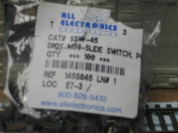
I used a double pole double through mini-slide switch from All Electronics. <!-- m --><a class="postlink" href="http://www.allelectronics.com/">http://www.allelectronics.com/</a><!-- m --> Item #ssw-45.
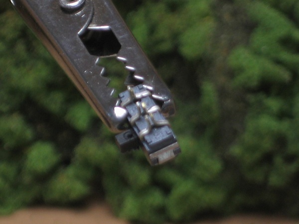
I first bend and solder the tabs together turning it into a single pole double through switch. I don't know the amperage value of the switch so combining the "like " poles makes the switch a little more heave duty. I have also drilled a small hole in the switch handle that will be used to attach it to the switch rod.
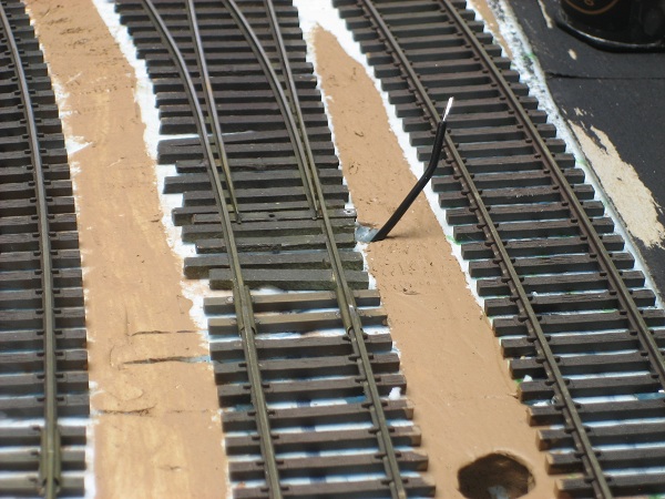
I pass a tinned wire that connects to the isolated frog through a 1/8 inch hole drilled next to the tie behind the switch rod tie. There is also a corresponding hole drilled in the switch rod.
I used a double pole double through mini-slide switch from All Electronics. <!-- m --><a class="postlink" href="http://www.allelectronics.com/">http://www.allelectronics.com/</a><!-- m --> Item #ssw-45.
I first bend and solder the tabs together turning it into a single pole double through switch. I don't know the amperage value of the switch so combining the "like " poles makes the switch a little more heave duty.
I pass a tinned wire that connects to the isolated frog through a 1/8 inch hole drilled next to the tie behind the switch rod tie.
My other car is a locomotive, ARHS restoration crew


