Posts: 2,724
Threads: 160
Joined: Dec 2008
Hi all, it's time for me to toss my hat into the ring.. For this challenge I'm going to complete a stalled project ( i hope ). My two 2-10-0 camelbacks.
<!-- l --><a class="postlink-local" href="http://www.the-gauge.net/forum/viewtopic.php?f=17&t=5279">viewtopic.php?f=17&t=5279</a><!-- l --> I haven't touched it in quite some time ,and really want to get it done. As you can see my last post on it was from back in October , just before the hurricane hit. I haven't even looked at it since then, and have plenty to do, and a bunch of supplies to use on them.
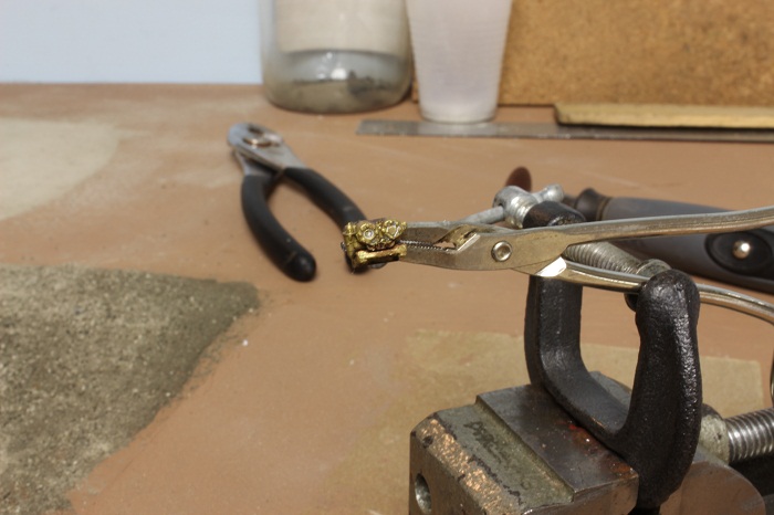
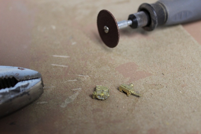
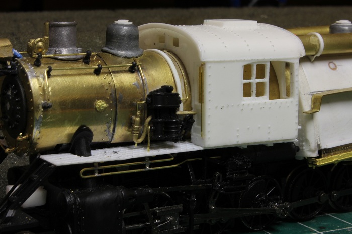
The first thing I got to was to mount some stoker motors on the break-man's side of the loco near the fireman's position. These parts are meant for a standard cab loco and not for center-cabs, so I had to alter the Call-Scale castings #190-224 with a Dremel cut off wheel. used a pair of pliers to hold the casting in place while I cut them.

the parts were cut in two so that I could fit them property in the correct position.
I clamped them in position on their brackets and soldered them together
I drilled out the frames for the mounting bracks and glued them in place with some CA.
My other car is a locomotive, ARHS restoration crew
Posts: 2,724
Threads: 160
Joined: Dec 2008
The next thing to do was the air and steam lines that feed in and out of the compressor. I got a drawing of the cross compound air pump piping from here. <!-- m --><a class="postlink" href="http://trainperson99.home.comcast.net/~trainperson99/brakes.html">http://trainperson99.home.comcast.net/~ ... rakes.html</a><!-- m --> They were formed out of some brass wire that scales out to about 1 1/4 inches in diameter. These pipes normally range from 1 1/8 to 1 1/2 inch so I felt that this was close enough.

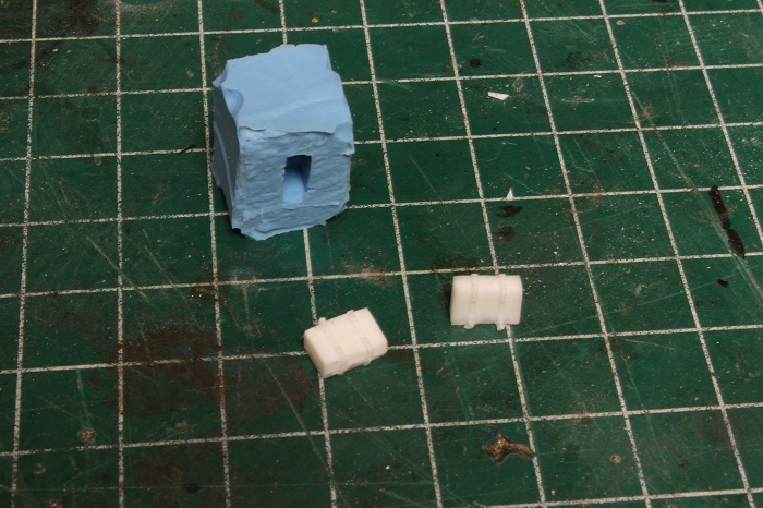
From there I moved on to a detail that was originally meant for my CNJ 2-8-0 that was featured in last June's issue of Railroad model craftsman but was not correct enough for the CNJ loco. But this is a freelanced model so it works just fine...I based the cab signal and train control system off of the CNJ's composite system of ATC speed & ATC stop. I'll go more into that later, but the box that I fabricated to hold the automatic train stop equipment on my 2-8-0 was too small, so it was rebuilt to the correct size. This left me with a unusable mold, or so I thought. I managed to find my old mold but not my master  ...I built that by starting with an O scale suitcase, cutting off the handle, and adding hinges & straps to it from styrene. When I mixed up some resin I got this..
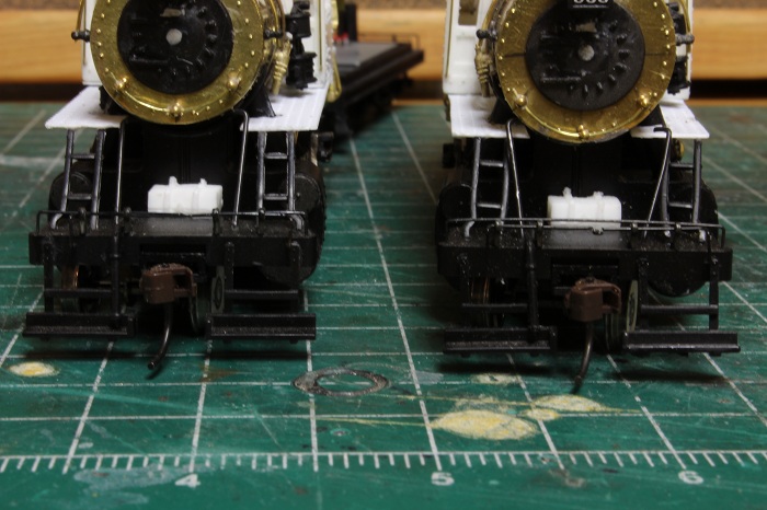
it was the first time I used this mold and I was happy with the results. This cabinet was then placed on the pilot deck where it belongs.
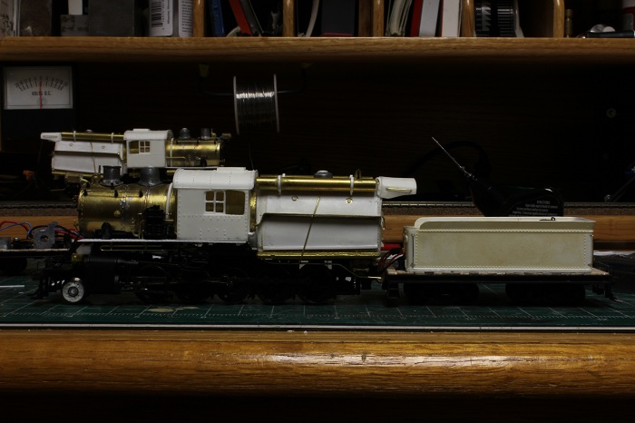
From there I moved on to the tender. I wanted to use an older style tender to emphasize that this loco was rebuilt several times over it's career, but retained it's original tender.
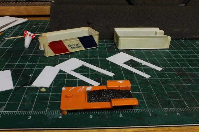
I took some Tyco old time 2-6-0/4-8-0 tenders and rough cut off the parts that I didn't need. The tender frames will need to be shortened to fit the new cisterns, but that is work for another day.
My other car is a locomotive, ARHS restoration crew
Posts: 2,724
Threads: 160
Joined: Dec 2008
I'll give the business end of the model a rest for a minute and do some more work to the tender. I used the old tender decks as a template and cut some new ones from scrap styrene. I did this because I wanted to eliminate the two tool boxes near the front of the model.

During my last bit of surgery I slipped with the saw and cut the lip of one of the tenders,,, so I started the repair on that also. I will also be removing most of the detail from the tenders.
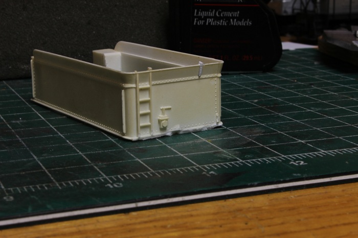
Lastly I wanted to experiment a little on these models.. For the rivet detail I used the rivet decals that are available from Micro-Marc. I have never used them be fore so we will see how they turn out.
My other car is a locomotive, ARHS restoration crew
Posts: 4,553
Threads: 100
Joined: Dec 2008
I haven't yet tried these rivets, but I have seen the result of their use, and it is excellent !!!
The only caution is, be careful handling the model once the rivets are in place, they are easily broken off. Things are better once the model is painted.
I went back to your original thread on the building of these locos, and I am truly impressed by how much impressive work you have already put into them !   I have tried some minor resin casting, and never liked the results. The details you've made are inspiring a revisit to resin casting, after a little more "education" on the process. ( yes, the secret to good castings, is perfect masters, well made molds, and patience. The first. I am basically capable of. The second ? I can learn, The third?  m a y be m a y be )
I can also see the impending critical need for me to purchase and learn how to use two new tools: A Rivet punch, and a Resistance solderer. The resistance solderer being the most needed. Iron, and torch soldering are fine for some very small detail parts, but the major assemblies?, especially after details are applied to them? OK wet tissue "heat sinks" are good, but not perfect. The rivet tool? I think I'll wait until I have played with the "rivet/decal" process.
Finally: One excellent model is amazing. Two, excellent identical models? That's mind blowing !!   
We always learn far more from our own mistakes, than we will ever learn from another's advice.
The greatest place to live life, is on the sharp leading edge of a learning curve.
Lead me not into temptation.....I can find it myself!
Posts: 2,724
Threads: 160
Joined: Dec 2008
Thanks for the kind words Sumpter,,I am a fan of your work also.
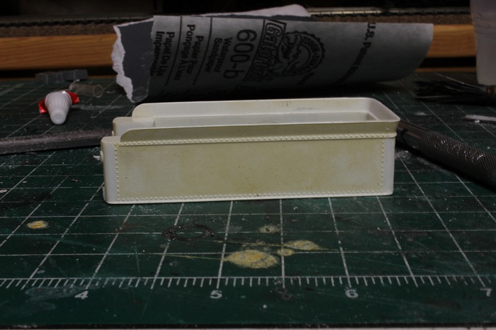
I did some more finishing sanding to the tender shells. I also removed the molded on grabs from them. I noticed that the two shells are of slightly different plastics. The Bicentennial one is a harder plastic ,as the other one is softer and has more pronounced rivet detail.
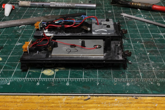
My next step was to remove the slight lip from the tender frame and sand it smooth.
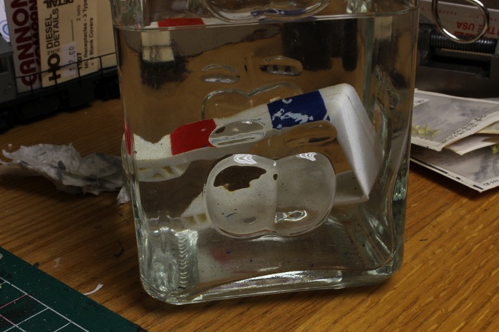
Now the other shell is soaking in some denatured alcohol so that I can strip the paint from it.
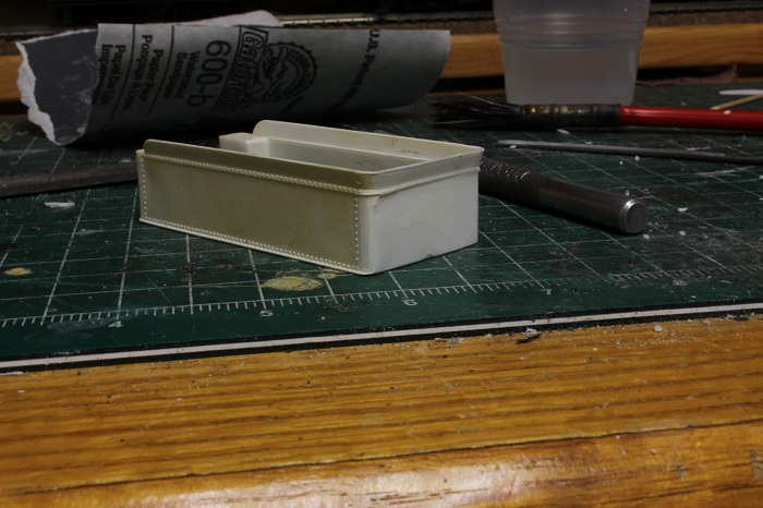
My other car is a locomotive, ARHS restoration crew
Posts: 2,724
Threads: 160
Joined: Dec 2008
Did a little more work on the 2-10-0's today..
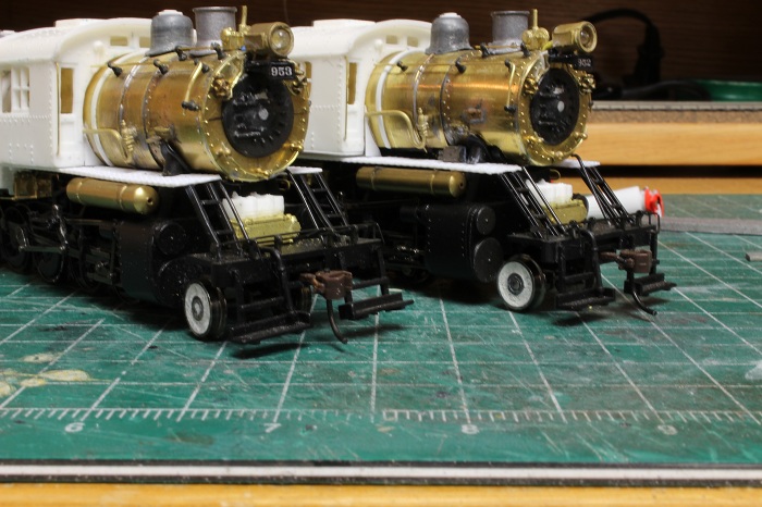
From this pic you can see that I have added a new air tank, Installed marker lights, mounted the supports that run from the boiler to the pilot, and changed the placement of the train control box on the pilot deck. It is now located on top of another equipment box for the "Speed" control. I had wanted to mount it high on the firebox, but it just didn't look right. The speed box found a home next to the Stop box, This was also a CNJ inspired location found on many of there locomotives. In the real world the Jersey central used this system on most of it's high volume mains to either stop a train if the engineer missed a signal or slow it down if the train was running over the posted speed.
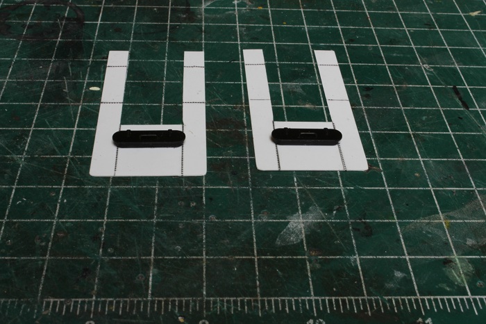
I have also filled in the holes in the tender frames that were use to mount the stock tender shells to them.

They will get some sanding when they are dry.
The water hatches were also salvaged from the old tenders and glued in place on the new decks.
My other car is a locomotive, ARHS restoration crew
Posts: 2,724
Threads: 160
Joined: Dec 2008
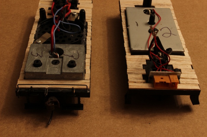
More tender work  -----Most older tenders had wood frames, usually made from oak with iron bracing. to simulate this I took some thin veneer and cut in into twelve inch withs ( a common with for this application ) and glued it down to the tender frame with some CA type glue. I tried to stagger the ends just slightly to accent that they are separate boards. If you get the chance check out some old tenders at a museum and you'll see this detail.
I have more pics to post ,,but now it's time for dinner ,so I'll post them latter.
My other car is a locomotive, ARHS restoration crew
Posts: 5,859
Threads: 175
Joined: Dec 2008
e-paw Wrote:.....I have more pics to post ,,but now it's time for dinner ,so I'll post them latter.
Oh, sure! You go to eat and leave us here, hungry for more.   
Wayne
Posts: 2,724
Threads: 160
Joined: Dec 2008
Sorry to make you wait doc. So, here's the rest.
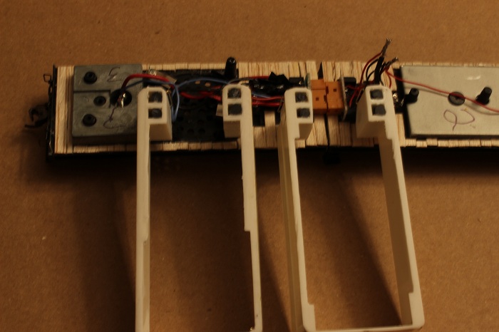
I plugged the open voids near the front of the tender shell with some old plastic sprue. This will give me something the drill and screw into in order to hold the new cisterns onto the tender frames. I will be drilling through the frames and installing screws from underneath the tender. This will allow me to remove them in kind of the same way that the stock ones did.
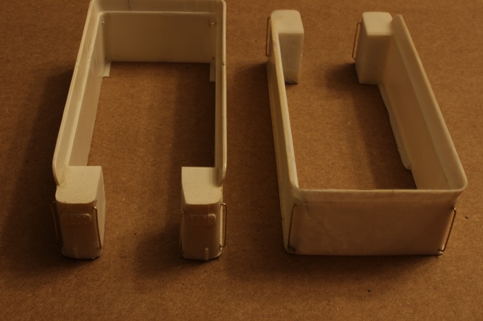
In this pic I have added the new grabs to the front and sides of the tender shells using some .015 brass wire.
My other car is a locomotive, ARHS restoration crew
Posts: 2,724
Threads: 160
Joined: Dec 2008
Along thew bottom edge of the tender shell I added a strip of styrene to bring up the height a little, It just seamed too short.

When this was dry I filed and sanded it flush to match the side of the cistern shell.
I placed the shell on the old frame and eye-balled the distance to the locomotive and measured the distance between the pins for the draw-bar. I will have to relocate the electrical connections further back on the frame and build the fireman's platform and coal bunker.
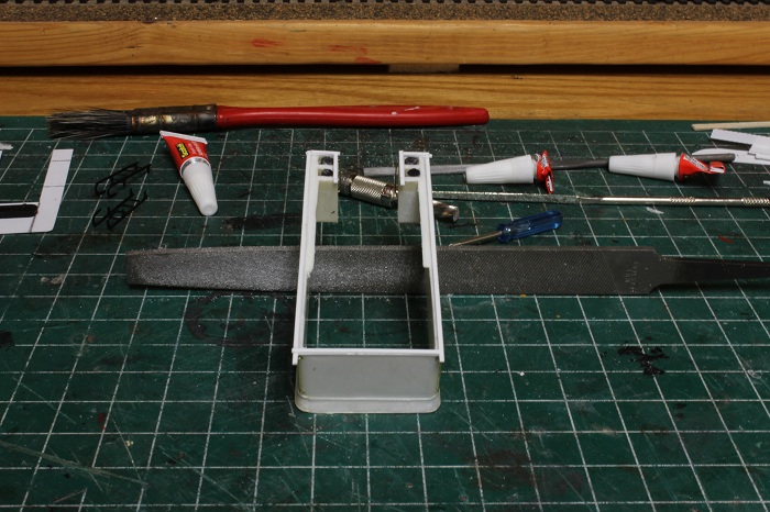
I marked the location for the new hole on the stock draw-bar and drilled it out on a drill press. when I did this I nut & bolted the two draw-bars together with 2-56 hardware, and used the larger hole to run a screw into a piece of scrap wood. This acted as a clamp to hold the assemble together for drilling.
My other car is a locomotive, ARHS restoration crew
Posts: 2,724
Threads: 160
Joined: Dec 2008
And the tenders continue.
I will go a little more in depth on how I am mounting the tender shells on the frames with these pics. I start by installing screws into the holes that I drilled and taped earlier. I was lucky that the screws clear the wheels, if they did not , I would have to grind down the top of the screws to allow the wheels to turn freely.

At the rear of the tender there is a plastic post for locating the weight, this tender has two, the other has one. That was drilled out to clear a 2-56 screw.
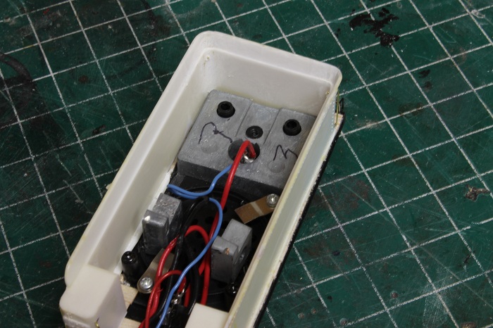
I cut a thick scrap of styrene to fit the rear inside dimension and glue it in place over the posts. this formed a kind of brace to hold the shell to the frame. The glue was only placed on the edges of the brace and not where the post touches it.
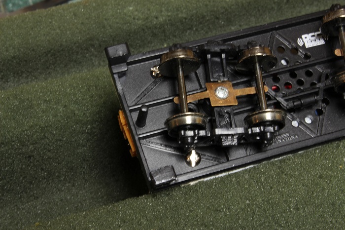
When It's dry I will drill and tap the brace for a 2-56 screw and attach it from the bottom as I did in the front.
My other car is a locomotive, ARHS restoration crew
Posts: 2,724
Threads: 160
Joined: Dec 2008
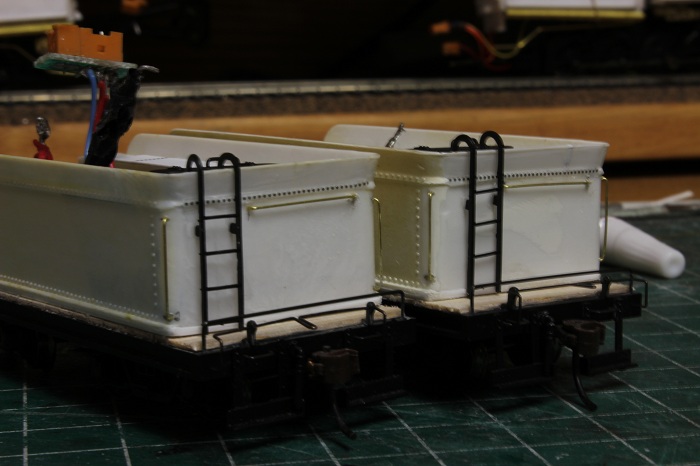
while that sets up I worked on the rear of the cisterns. Ladders were added along with a row of rivets that I had to remove earlier.This was done with the ladder from the stock tenders and more of the rivet decals. I did have some trouble with keeping the rivet decals on the tender. They do not stick well as Sumpter had stated. A little dulcoat sprayed over them does a lot to keep them in place.
I have also installed a horizontal grab across the back of the tender.
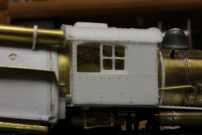
I also started on the cab interior on the engineers side of the center cab and I ran a little more air piping under the walk way on the same side.
My other car is a locomotive, ARHS restoration crew
Posts: 1,682
Threads: 101
Joined: Dec 2011
Great work on those tender. I like your attention to small details like the wood decking. Gonna pays off on the completed model. Very inspiring!
Matt
Posts: 5,263
Threads: 195
Joined: Apr 2009
The wooden deck is a surprise to me. That means the prototype built a base iron frame, put a wooden deck on top and mounted the coal and water supply as an independent unit on top of the deck. That explains to me why so many tenders have been used as a base for caboose etc. at a later time.
Reinhard
Posts: 4,553
Threads: 100
Joined: Dec 2008
I haven't yet found any reliable references about the wood decking that the tender water tank/coal bin sat on, so what I offer here is more conjecture than fact.
Simply put, the wood decking was there to support the bottom of the water tank, evenly across its front to back and side to side dimensions. This practice was done away with when cast "waterbottoms" came into use, as they were strong enough to not require additional support, and were an integral part of the frame. the wood decking also helped distribute the weight of the fuel ( coal, or oil ) better along and across the tender's otherwise open frame. Part of the normal locomotive overhaul, would have been the removal of the tender body, and the replacement of the wood decking.
It is good to see that detail being modeled here !   
We always learn far more from our own mistakes, than we will ever learn from another's advice.
The greatest place to live life, is on the sharp leading edge of a learning curve.
Lead me not into temptation.....I can find it myself!
|
 the parts were cut in two so that I could fit them property in the correct position.


 ...I built that by starting with an O scale suitcase, cutting off the handle, and adding hinges & straps to it from styrene. When I mixed up some resin I got this..


 -----Most older tenders had wood frames, usually made from oak with iron bracing. to simulate this I took some thin veneer and cut in into twelve inch withs ( a common with for this application ) and glued it down to the tender frame with some CA type glue. I tried to stagger the ends just slightly to accent that they are separate boards. If you get the chance check out some old tenders at a museum and you'll see this detail.

