E-paw's duff challenge for 2013
#16
Well Sumpter I never looked into the 'why' only that it is there. But , the cast water bottom sounds plausible to me. Thanks for the input.


I started on the Coal bunkers yesterday. If you look at the picture of the one on left you can see the support that holds the tender shell to the frame.
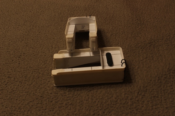


I have filled in some of the gaps with squadron putty that will have to be sanded down.
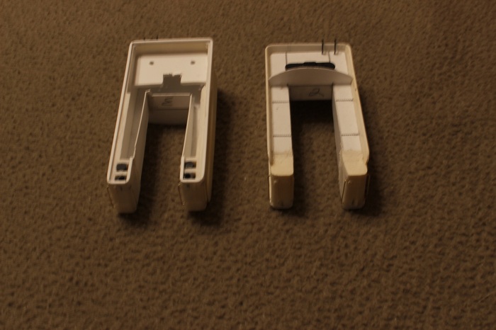
   

The bottom of the bunker will remain open and will be covered with some foam shaped to the contours of the coal load. I have decided to completely remove the harness that are for the DCC plugs and replace it with just a single two wire plug. I post pics of that tomorrow.
 My other car is a locomotive, ARHS restoration crew  
Reply
#17
And the work continues,,, Big Grin

I worked some more on the coal bunker and coal load today. I started by cutting a template from paper for the foot plate that runs into the floor of the coal bunker.     when I was satisfied I transferred it to some diamond tread styrene and glued it to the tender frame. I also added some steps that were bent from some thin brass. The space under the foot plate will remain open to allow room to rum the wire for the tender pick up.

   
This only makes up half of the foot plate, the rest of it was cut from the same material as the tender portion and glued in place under the firebox backhead.     As you can see I still need to modify the wiring on one of the engines.

    I also carved the sub-base for the coal load from some foam. This will eventually be painted black and covered with coal. There are only a few more things to get to before painting, this project is starting to come along nicely.
 My other car is a locomotive, ARHS restoration crew  
Reply
#18
They look great!! Smile Smile
~~ Mikey KB3VBR (Admin)
~~ NARA Member # 75    
~~ Baldwin Eddystone Unofficial Website

~~ I wonder what that would look like in 1:20.3???
Reply
#19
This is an amazing build to follow. I can't wait to see them done.
Reply
#20
e-paw Wrote:this project is starting to come along nicely.
Been like that since the beginning Cheers
Tom

Model Conrail

PM me to get a hold of me.
Reply
#21
Almost there,,,,, I have moved on to the tender lighting. I drilled out the bottom of a Shelly Castings headlight to fit a small LED. This will provide me with directional lighting .    


In order for the light to clear the read lip of the tender the SH&D crew had to build a simple stand from styrene to mount the fixture to. I insulated the LED leads with some liquid electrical tape.    


The lights were mounted on the tender deck just right of center.    

From there I moved on to the rear railings for the firebox walkways.     This method is one that I have posted about several times before. I draw out the railings on a scrap of wood , tape down the brass wire in place , and solder away.

When your finished you end up with a nice set of railings    
 My other car is a locomotive, ARHS restoration crew  
Reply
#22
I mounted the railing in place by soldering them to the walkways..    

This underside shot shows the attachments a little better.    

The last detail that I wanted to add was the magnetic impulse collector coil. This futuristic sounding device is what picks up the signals from the rails for the automatic train stop system.     It gets mounted at the rear of the engine frame on the engineers side of the loco.

Now the 2-10-0's are ready for paint. Here they are sitting at the east end of AT yard where they will be assigned.    
 My other car is a locomotive, ARHS restoration crew  
Reply
#23
Worship Worship Worship
Reply
#24
Excellent progress, funny looking critters but I have always liked the looks of em'. Eek
Mike

Sent from my pocket calculator using two tin cans and a string
Reply
#25
Great lookink models! Great work! I'm envious, a little bit.

And happy birthday, Steve!
Cheers, Bernd

Please visit also my website www.us-modelsof1900.de.
You can read some more about my model projects and interests in my chronicle of facebook.
Reply
#26
Nice work, Steve. Thumbsup Thumbsup

Wayne
Reply
#27
Thanks everyone. My biggest difficulty now will be the weather.. I do all my airbrushing outside and, it look likes the weather will not be very cooperative at least for the next week or so. The next step, painting, will depend on mother nature's schedule.
 My other car is a locomotive, ARHS restoration crew  
Reply
#28
Dont worry bout the weathering, just sit back and drink a cold one, happy birthday

548 548 548
Tom

Model Conrail

PM me to get a hold of me.
Reply
#29
Great engines you have created! Thumbsup Thumbsup Thumbsup

Lutz
Reply
#30
Almost had the chance to paint them today, Nope, but it started to snow just as I got home from work. So I'll post what I've been up too.

I had this idea floating around in my head now for a few months and decided to use it on this model. I wanted to give a try at building one of these...<!-- m --><a class="postlink" href="http://www.gingerb.com/LNE%20Bethlehem%20Tender%20Booster%20Truck.jpg">http://www.gingerb.com/LNE%20Bethlehem% ... 0Truck.jpg</a><!-- m -->
A Bethlehem tender booster truck. My big hang up was to come up with a way to make the side rods turn with the wheels. My solution was to start with one of the Kato freight trucks that have the spinning bearing caps, and modify it for side rods.

I started by putting a file to the side frames to get as thin as I could, that way I can add styrene over them to build the new side frames.    


I next cut some thin styrene in the shape of the new side frames and attach them to the trucks with Model Masters ca glue.     this stuff works great for bonding to the slippery surface of the Kato trucks. The important thing here is to make sure that the new side frames clear the bearing caps and to not glue them to the trucks either.

For the counter weights, I cut them from the same plastic as the side frames carefully marking the center point. I filed off the details from the bearing caps and drilled out the center hole from the back side out so that it would be a close to dead center as I could make it.     Here is a front and back view of a pair of them to help you understand what I am doing. I used a plastic rivet from Tichy to act as a centering pin and glued them together with more of the same CA. when it was all dry I drilled out the bearing caps to the original depth and sanded off the head of the rivet.

I cut the side rods from some U-channel sanded the ends flat and drilled them out to accept some Bowser valve gear rivets     I also drilled the other end of the counter weights for the same valve gear rivets. then it was all put together, and tested for binds. I'll post a video of it in just a few.
 My other car is a locomotive, ARHS restoration crew  
Reply


Forum Jump:


Users browsing this thread: 1 Guest(s)